Autonomous Maze-Solving Robot

Partner Project with Kyle Tran ↗ · Raspberry Pi Pico · MicroPython

Raspberry Pi Pico MicroPython Tank Drive Autonomous Navigation Completed
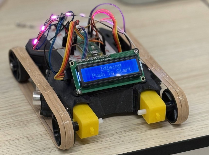
The finished maze-solving robot: tank tracks, yellow gear motors, an LCD status screen, and a Raspberry Pi Pico on a breadboard
The finished robot: tank drive, Pico on a breadboard, LCD status screen
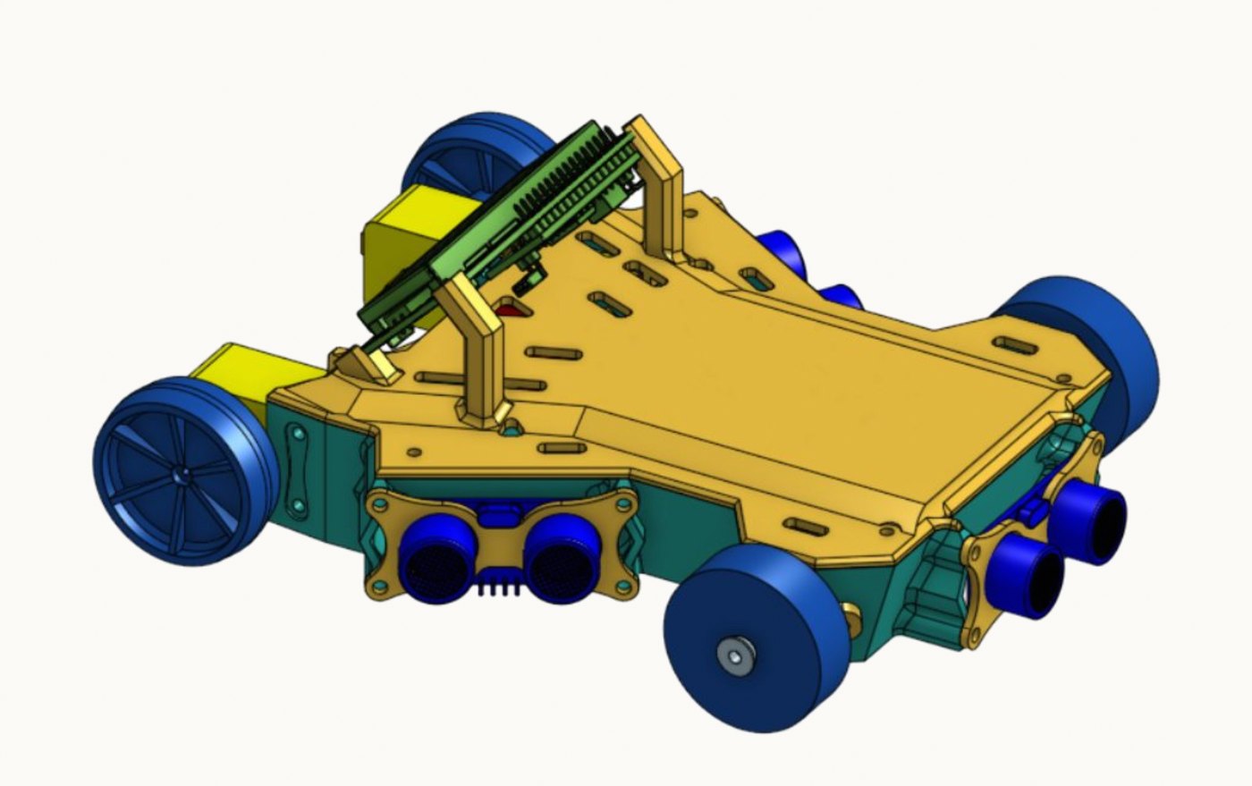
Onshape CAD render of the robot chassis with wheels, ultrasonic sensors, and the Pico mount
Full robot CAD in Onshape (design by Kyle Tran)

A Two-Person Build

Built October–December 2025 with my classmate Kyle Tran — a tank-drive robot that autonomously maps and solves a previously unseen maze. The system runs concurrent sensor polling, motor control, and real-time pathfinding on a single Raspberry Pi Pico (MicroPython + asyncio) without blocking the navigation loop, building an internal map of visited cells and backtracking to explore unvisited branches until it finds a way through.

The platform uses ultrasonic and IR sensors for wall/obstacle detection, a tank-drive dual-motor configuration, an I2C LCD with status LEDs for live feedback, and a bench potentiometer for tuning behavior without reflashing firmware.
My Contributions

Kyle led the robot itself: he designed the full robot in CAD and wrote all of the MicroPython firmware. My part was the early concept sketches of the chassis and the test maze the robot had to solve. I laid the maze out and dimensioned it in AutoCAD and designed the 3D-printed corner brackets that join its walls. I also modeled a handful of smaller robot components while learning CAD from Kyle.

Full credit for the robot's CAD and firmware belongs to Kyle. His writeup is linked below.

How It Navigates

Sensing
  • Ultrasonic sensors for wall/obstacle distance
  • IR sensors for line-following and proximity
  • I2C LCD + status LEDs for live feedback
Control
  • Raspberry Pi Pico, MicroPython + asyncio
  • Concurrent sensing, motor control, and pathfinding
  • Bench potentiometer for tuning without reflashing
Navigation
  • Tank-drive dual-motor platform
  • Builds an internal map of visited cells
  • Backtracks to explore unvisited branches

From Sketch to Maze

My side of the build: the early concept sketches and the test maze itself, from the AutoCAD layout to the 3D-printed corner brackets that join its walls.

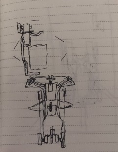
Hand sketch of the chassis from above, with angled sensor mounts
My concept sketch: chassis from above with angled sensor mounts
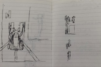
Notebook pages of early robot and component sketches
My early concept sketches
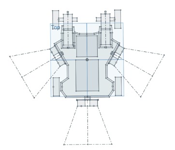
Top-view chassis sketch with dashed cones showing each ultrasonic sensor's field of view
Chassis sketch with each ultrasonic sensor's field of view
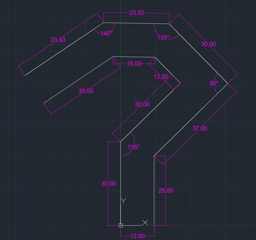
AutoCAD drawing of the test maze with wall lengths and angles dimensioned
Test maze I laid out and dimensioned in AutoCAD
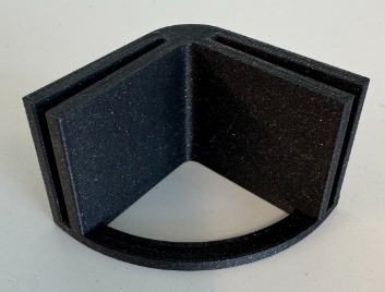
Black 3D-printed slotted 90-degree corner bracket
3D-printed corner bracket I designed to join the maze walls
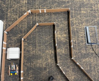
Overhead view of the cardboard test maze with the robot inside
The finished test maze, with the robot inside
Robot Design & Firmware Credit — Kyle Tran
For the full writeup, CAD, and firmware, see Kyle's portfolio, the Onshape CAD, and the firmware repository.